Head Motion in fMRI and Anatomical MRI
Motion Suppression Strategies
- Characterization of Head Motion: Careful study of head motion during motor tasks, particularly in stroke patients, and the development of behavioural tasks designed to reduce head movement during fMRI. Development of fMRI
- Simulators: The creation of realistic fMRI mock-up systems that c can be used to optimize experimental designs or train individuals to remain still prior to scanning. Optical Position
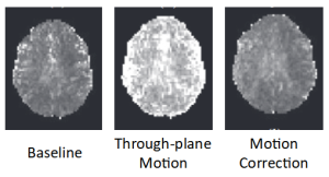
- Tracking Systems: Use of high-resolution tracking systems to measure head motion in real-time. We have designed and constructed several such MRI-compatible tracking systems that can adaptively move the scan plane based on tracking data, significantly reducing motion artifacts and enhancing image quality.
Featured Work
Explore the captions for further details.
")
")
Recent Publications
Sensors, 24(12), 3737. https://doi.org/10.3390/s24123737
Frontiers in Neuroscience, 13, 462471. https://doi.org/10.3389/fnins.2019.00825
World Neurosurgery: X, 2, 100021. https://doi.org/10.1016/j.wnsx.2019.100021
Brain Connectivity, 8(2). https://doi.org/10.1089/brain.2017.0491
Magnetic Resonance Imaging, 34(8), 1206–1219. https://doi.org/10.1016/j.mri.2016.06.005
Journal of Neuroscience Methods, 270, 46–60. https://doi.org/10.1016/j.jneumeth.2016.06.005
PLoS ONE, 11(6), e0156750–e0156750. https://doi.org/10.1371/journal.pone.0156750
Magnetic Resonance in Medicine, 69(3), 734–748. https://doi.org/10.1002/mrm.24309
Medical Physics, 38(8), 4634–4646. https://doi.org/10.1118/1.3583814
Magnetic Resonance in Medicine, 53(1), 141–149. https://doi.org/10.1002/mrm.20319
NeuroImage, 14(2), 284–297. https://doi.org/10.1006/nimg.2001.0829